
Industry veteran Arthur Kelm explores the definition of clean power, including motor loads, sensitive electronic loads, and lighting and convenience loads.
After working over 43 years in the professional recording industry and the past 12 years of that involved in the high end A/V market, I have lost track of the number of times I have heard the term “clean power” used to describe someone’s power system. Whenever I raise the question “What do you mean by clean power?” I have never heard the same answer twice. It is like asking, “What is the best way to ground an audio and video system?” Everyone has their own interpretation.
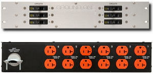
Ground One power distribution unit PD620 shown above.
The reality is, you can define “clean power” through testing and measurements. The same holds true for “grounding systems.” I have compiled over 200 performance and noise readings of systems over the past 12 years, everything from industrial warehouse developments, to world-class production facilities in Los Angeles, condominiums in The Four Seasons hotel in San Francisco, to the upper east side of New York City and many points in between.
From my personal experience, I know that power and grounding is the heart of any electronic system. Keeping voltage distortion, current harmonic, normal mode noise and common mode noise to a minimum in a power distribution system, is ABSOLUTELY necessary for reliable operation. This is even more true for hard drive based audio and video systems. The unfortunate reality is that utility power and generator power and solar power is, simply put, not adequate for critical load applications.
Thinking About Power in a Different Way
In order to control power quality, one has to first look at the source of your power and how it is being distributed around your facility/system. For years, sensitive electronic loads have been segregated from other equipment in the recording and post-production environment (sometimes not exactly correctly).
I would suggest that we define and apply a minimum performance standard for all electrical systems that feed critical loads. I would also take this practice and include heavy technology driven homes.
I have been involved in homes that have over $2,000,000.00 in sensitive equipment installed. Ideally all loads need to be divided into categories and isolated from one another. When engineering a new system, I would suggest that we then define loads into three basic categories.
Proposed categories:
1. Motor loads (refrigeration, air conditioning and water pumps)
2. Lighting and convenience loads (microwaves, coffee makers, dimming circuits, etc.)
3. Sensitive electronic loads (control systems, audio and video equipment)
Motor Loads: If we were to put all of our motor loads on the same panel (or sub panels), we would be able to control the negative effects of spikes and dips that are common whenever a motor starts up (this is common when you see your lights dim when an air conditioning unit turns on). Having dedicated panels and circuits will eliminate this problem. The next benefit to this approach allows us to add “Power Factor” correction to the system. All motors are inductive loads; the efficiency of the load is measured in PF (power factor). The goal is to achieve a number of 1 or 100% efficiency. When power factor correction is added to a system, the system is more efficient and leads to lower electrical bills. It also extends the life of the equipment. This solution can only be achieved when loads are isolated.
Lighting and Convenience Loads: These loads are generally not a problem. The exception is florescent light ballast and SCR dimmer circuits. Keeping these loads separate from other loads will make any negative effect much simpler to isolate and solutions simpler to engineer.
Sensitive Electronic Loads: These are the most critical loads to protect and condition. They require at a minimum the following:
1. A properly engineered and installed grounding system.
2. Electrostatic triple shielded isolation transformer, including RF filtering along with spike and surge suppression (TVSS).
3. Breaker panel with high quality bolt-in breakers, copper bus bars and isolated ground bus bar.
4. Additional high quality TVSS and filtering installed in panel board.
5. Stranded wire to feed receptacles.
6. Hospital grade receptacles.
Electrical wiring should be a minimum of 12 gauge for a 20 circuit. I prefer to up-gauge all wiring one size and make all the conductors the same gauge. My first choice is to run wiring in ridged or flex steel conduit. Second choice is steel MC cable.
The next factor to consider is the length of wiring to the receptacle. I recommend that the power panel be located as close as possible to the main components of the system. This allows the impedance of the system to be as low possible. In studio and theater applications, this should be kept to less than 50 feet. For audiophile/stereo applications, wire should not exceed 20 feet.
The above recommendations should be the foundation of any system. Depending on your specific needs, additional power conditioning may be required. The most basic conditioning (after TVSS an RF filtering) is voltage regulation. This will be required if you are in an area that has reoccurring utility power fluctuations. Regulation can be accomplished a few ways.
The most basic is a stepper transformer. These types of units monitor the output voltage of the transformer and changes taps on the primary of the transformer to adjust the output to the proper voltage.
The next option would be to use an inverter system. This unit’s approach is to takes the incoming AC voltage and turns it to DC then converted back to AC again, generating a new low distortion sine wave. The third approach would be a “full on line” UPS system. This is basically an inverter system with batteries.
Setting a New Standard for System Performance
I would like to now put some numbers to what I would be defining as a “clean power” system. (These measurements were taken with a Powervar Power Probe115 and Fluke 43 Power Analyzer)
System With No Load
1. Common Mode Noise: Less than 50mv
2. Normal Mode Noise: Less than 10mv
3. Voltage Distortion: Less than 1.5%
4. Resistance to Earth: Less than 5 Ohms
System With Load
1. Common Mode Noise: Less than 150mv
2. Normal Mode Noise: Less than 50mv
3. Voltage Distortion: Less than 1.5%
4. Resistance to Earth: Less than 5 Ohms
The reason for the two different standards, is reflected noise from the individual components’ power supplies. One must consider that all power supplies have reflected noise. I refer to this as a component’s “footprint.” As with motors there are solutions to help correct these issues. I would consider a system achieving the above criteria a “Certified Ground One Power System.”
In closing, I understand that my views and recommendations may seem a bit extreme to some, however, I believe that in this day and age of overly hyped power products, there is a need to establish a minimum standard for power system performance.
Arthur Kelm is CEO of Ground One AV Inc., a consulting/engineering firm that addresses power and grounding solutions for professional recording facilities and high-end home installations. His list of clients reads like a who’s who of the entertainment industry (for more information Google “Ground One” or go to www.ground1.com). He is currently Director of Engineer for Capitol Recording Studios in Los Angeles, CA. He has been director of engineering for Record One (L.A.), The Complex (L.A.), Record Plant Studios (L.A.), Skywalker Sound (Marin, CA.) and consultant for Walt Disney Imagineering. He now focuses his energies on problem solving and creative solutions related to power quality issues.